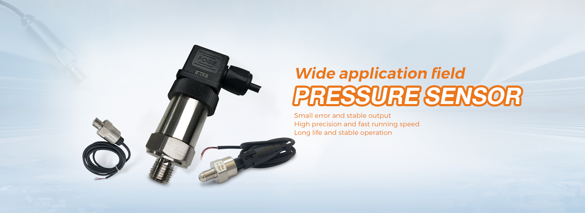
Pressure transmitter
1. Pressure and negative pressure measuring devices should not be installed in curved, corner, dead corner, or vortex shaped areas of the pipeline, as they are installed in the straight direction of the flow beam, which can cause distortion of the static pressure head.
When installing pressure or negative pressure measuring devices, the pressure measuring pipe should not extend into the interior of the fluid pipeline or equipment due to being perpendicular to the flow beam. The pressure measuring port should have a smooth outer edge and there should be no sharp edges. Continuous use of pipes and fittings should be neatly cut and burrs removed.
3. The installation position of pressure tapping pipes on horizontal and inclined pipelines should be at the upper part of the pipeline when the fluid is gas.
When the fluid is liquid, it should be within an angle range of 0-450 between the lower half of the pipeline and the horizontal centerline or on the centerline of the pipeline. When the fluid is steam, it is within an angle range of 0-450 between the upper half of the pipeline and the horizontal centerline or on the centerline of the pipeline.
4. All pressure tapping devices must be equipped with a primary door, which should be close to the pressure tapping device.
5. The horizontal section connecting the pressure pulse pipeline should maintain a certain slope, and the direction of inclination should ensure the discharge of air or condensate. The pipeline slope requirement is that the pressure pulse pipeline should not be less than 1:100. The pressure pulse pipeline should be equipped with a drain valve at the pressure gauge to flush the pipeline and remove air.
6. Before installation, the pressure pulse pipeline should be purged to ensure cleanliness and smoothness inside the pipeline. The valves on the pipeline should undergo a tightness test before installation, and after the pipeline is laid, another tightness test should be conducted. Before driving, the pressure pulse pipeline should be filled with water (be careful not to allow bubbles to enter during water filling and affect measurement).
Flange type liquid level transmitter
1. The transmitter should be installed at the bottom of the pool where the liquid level needs to be measured at another location (not connected to the discharge port).
2. The transmitter should be installed in a place where the liquid is relatively stable, avoiding and away from turbulence equipment (such as mixers, slurry pumps, etc.).
Input type liquid level transmitter
When installing in static water, such as deep wells or pools, the method of inserting steel pipes is generally used. The inner diameter of the steel pipe is within ф Around 45 mm, the steel pipe is drilled with several small holes at different heights to facilitate the smooth entry of water into the pipe.
2. When installing in flowing water, such as waterways or continuously stirred water, insert the inner diameter into the ф Drill several small holes on the opposite side of the 45mm steel pipe at different heights in the direction of water flow to allow water to enter the pipe.
3. The installation direction of the transmitter is vertical downward, and the transmitter should be placed away from the liquid inlet and outlet and the mixer.
4. If necessary, wire can be wrapped around the transmitter and vibrated up and down with the wire to avoid breaking the cable.
Post time: Apr-30-2024


